This is the first entry in a build blog for an OpenROV, serial number 66. I'm building it for my brother, Conal True, Professor of Aquaculture at the University of Baja California, Ensenada, Mexico for use in his
Totoaba research program.
Here are the unboxing photos:
Everything comes tightly backed in a sturdy cardboard box.
The housing is serialized. #66 for mine.
Platform rotation servo.
Connector block for thruster power.
Pressure relief syringes for endcaps.
LEDs for camera light.
Miscelaneous hardware.
Battery contacts.
CAT5E single pair tether/ethernet.
Rings for thruster housings.
OpenROV cape. A captive Arduino clone for realtime control
Beaglebone, ARM based Linux single board computer.
Thruster components.
Motor controllers. Digital interface between thrusters and computer.
1080 resolution camera.
Battery holders and endcaps. Sand/debur these before starting build.
Plastic components.
Central tube and endcap components.

Note the small crack. I'll try infusing with a little of the plexiglass cement.
Power connectors.
Battery and thruster wire.
Ethernet baluns.
USB right angle.
O-rings (labelled belt)
Miscelanneous bits.


 Camera mount with LED shields added. These shields keep the glare of the forward facing LED arrays from interfering with the camera.
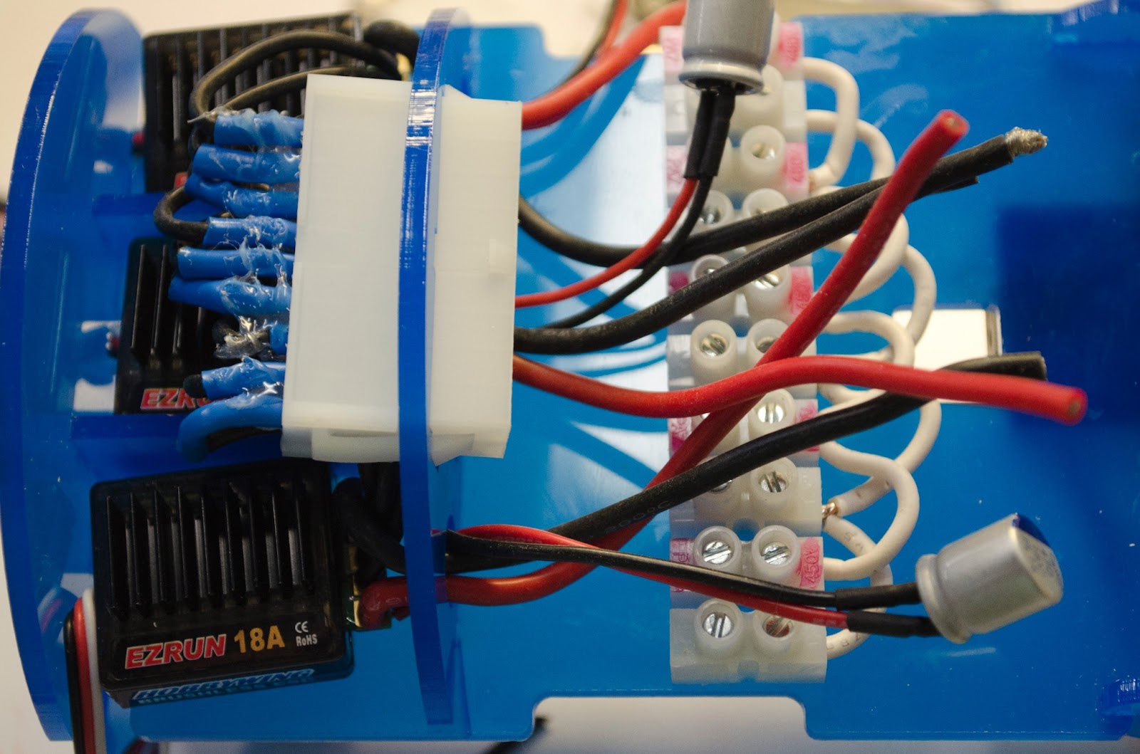
 The motor controllers are mounted in a group of three on the side away from the Beaglebone.
 The end cap is tricky to put on. Glue on the fingers means fingerprints on the plastic.
 The Beaglebone goes on this side. The plastic arrived pre-discolored for my convenience. I don't think the fish will care.
 The other end piece is asymetric. The servo mounts offset with the axis in line with the center of the tube.
 The whole platform should be square, which is tricky. If you were building more than one you would get good at this part.
 It does slide into the tube, and rotates fairly smoothly. I'm worried about whether the servo will be strong enough to rotate the whole platform.
 The camera mounts on the back of platform, and is held down with zip-ties. These are not the reusable ones that come with the kit.
 The LED arrays are glued down. I used five minute epoxy. I glued a short strip of zip-tie tip to the ring of the lens, which allows manual focus. The lens ring is hard to manipulate without some sort of handle.
 The OpenROV cape fits onto the Beaglebone. Watch out for bent pins (often happens on the outside pins). Straighten carefully before seating the cape. This takes a good bit of force.
 These are the components for the tilt servo. There were no instructions in the assembly video, and none of the mounting components appear to be used.
 Instead, use these four pieces.
 I found it easier to put the nuts on the outside. Tighten with a nut driver, or use small pliers.
 The whole assembly is held together with a reusable zip-tie. The camera platform is held down by the pressure of the tube.


 Note the small crack. I'll try infusing with a little of the plexiglass cement.
